How does your company provide in-house training for new and young employees?
You may sometimes find it difficult to put a question to your busy boss or senior colleague.
To solve the problem, we will pick out the indicators to be emphasized in model selection from an actual catalog, and explain them so that even young employees can understand easily.
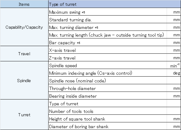
Table 1 below is a specification list in a TAKISAWA product catalog.

Table 1 Excerpt from “TCN-2100”
Among the above items, we will pick out “Max. turning diameter”, “Max. turning length”, “X-axis”, and “Z-axis”, which are important words to understand the items “Capability/Capacity” and “Travel”.
1. Overview of machine configuration

Fig. 1 Machine configuration schematic diagram
JISB-0106:2016 defines machine configuration as follows.
- Spindle: A shaft that rotates a workpiece attached to it
- Headstock: A base equipped with a spindle that rotates a workpiece
- Turret: A base to which cutting tools are attached
- Carriage: A base that consists of apron, saddle, cross slide, and turret, and reciprocates on the bed to feed cutting tools
- Tailstock: A base that is opposite to the headstock on the bed, and supports one end of a workpiece
The machine in Fig. 1 is equipped with a tailstock, which supports one end of a workpiece when machining it.
The tailstock is used to prevent runout of the rotation center shaft.
Particular attention is necessary when machining an asymmetrical or long workpiece.
We hope you understand the components of a machine.
※”JIS” stands for “Japanese Industrial Standards” and is the Japanese national standard for industrial products.
2. Components related to “Capability/Capacity” and “Travel”

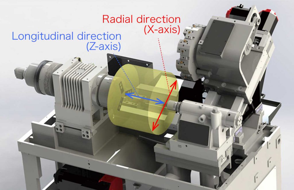
Fig. 2 Schematic diagram of axis directions
Fig. 2 shows the max. turning diameter (red) and max. turning length (blue).
Max. turning diameter is literally the maximum turning diameter of workpieces that can be turned by the machine.
Max. turning length is similar to the above with regard to length.
3. X-axis and Z-axis
The coordinate axes of an NC lathe are defined by JISB-6130:2003 as shown below.
- Z-axis: Parallel to the machine spindle
- X-axis: Horizontal as far as possible
In JISB-6130:2003, the X- and Z-axes are defined to form right-handed Cartesian coordinate system.
To easily build up an image, we give a supplementary explanation.
Explained using Fig. 2 based on JISB-6130,
Z-axis is interpreted as an axis in the spindle longitudinal direction, and indicated by the blue line in Fig. 2, and
X-axis as an axis orthogonal to the Z-axis and also a radial axis of the workpiece.
For the machine configuration in Fig 2, the carriage is slanted and the carriage movement direction is the X-axis indicated by the red line.
How was today’s explanation?
Please look forward to the next column, which will explain the items related to spindle and turret!
Many terms have appeared in this column. To learn other terms, click Machine Tool Terminology!
